


 Quick Add
Wiring Instructions RJ45
RJ45 Wiring Guide for CAT5e and CAT6 Euromodules
This guide explains how to wire RJ45 CAT5e and CAT6 Euromodules using the T568A and T568B wiring standards. It is intended to help installers terminate data outlets, patch panels and RJ45 connections consistently.
Key principle: Use the same wiring standard at both ends of the cable. For most new installations, T568B is commonly used, but T568A is also valid where the existing installation or project specification requires it.
Which Wiring Standard Should I Use?
RJ45 network outlets are usually terminated using either T568A or T568B. Both standards use the same eight wires, but the green and orange pairs are swapped.
- Use T568B for most new standard network installations, unless specified otherwise.
- Use T568A where it matches the existing site wiring, customer specification or project requirement.
- Do not mix T568A and T568B on opposite ends of the same fixed cable unless a crossover cable is specifically required.
- Always keep the same standard throughout a structured cabling installation.
RJ45 Pin Numbering
When looking at the front of an RJ45 plug with the retaining clip facing away from you and the gold contacts facing upwards, pin 1 is on the left and pin 8 is on the right.
Installer note: Euromodules and keystone jacks normally show the T568A and T568B colour codes on the rear of the module. Follow the printed colour guide on the module, not the physical order of a loose RJ45 plug.
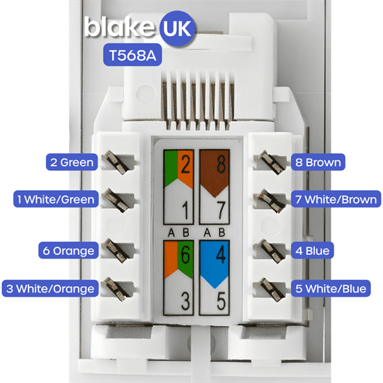
T568A Wiring Standard
T568A is commonly used where it matches an existing structured cabling installation, site standard or project specification. The diagram and table below show the correct conductor arrangement.
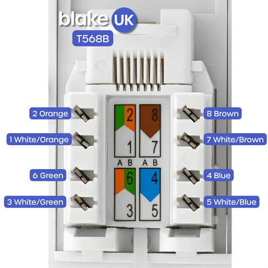
T568B Wiring Standard
T568B is commonly used for many new network installations. The diagram and table below show the correct conductor arrangement.
What is the Difference Between T568A and T568B?
The only practical wiring difference is that the orange and green pairs are swapped. The blue pair and brown pair remain in the same positions in both standards.
How to Terminate a CAT5e or CAT6 Euromodule
- Choose the wiring standard required for the job, usually T568B unless the site already uses T568A.
- Strip only enough outer cable sheath to dress the pairs into the module.
- Keep each pair twisted as close as possible to the termination point.
- Follow the colour code printed on the rear of the Euromodule.
- Punch each conductor fully into the IDC terminal using a suitable punch-down tool.
- Trim any excess conductor cleanly.
- Fit the module into the faceplate or back box without sharply bending the cable.
- Test the link using a suitable network cable tester.
Good Practice for Reliable Network Points
- Use the correct category of cable and module, for example CAT5e cable with CAT5e modules or CAT6 cable with CAT6 modules.
- Do not untwist more cable than necessary at the termination point.
- Avoid tight bends, crushed cable or excessive pulling force.
- Do not run data cable close and parallel to mains electrical cable where it can be avoided.
- Label outlets clearly, especially where several network points are installed.
- Test every terminated outlet before handover.